Silicon manganese alloy is mainly used as an intermediate material for the deoxidizer and alloying agent of steel production, and is also the main raw material for the production of low carbon ferromanganese. Its consumption accounts for the second place in electric furnace ferroalloy products. Silicon-manganese alloys with carbon content below 1.9% are semi-finished products for the production of medium and low carbon ferromanganese and electrosilicon-thermal metal manganese. Silicon and manganese in silicon manganese alloy, strong affinity with oxygen, in the use of silicon manganese alloy in steelmaking, the resulting deoxidation products MnSiO3 and MnSiO4 melting are 1270℃ and 1327℃ respectively, with low melting point, large particles, easy to float, good deoxidation effect and other advantages. Under the same conditions, using manganese or silicon deoxidation alone, the burn loss rate is 46% and 37%, respectively, while using silicon manganese alloy deoxidation, the burn loss rate of both is 29%. Therefore, it has been widely used in steelmaking, and its output growth rate is higher than the average growth rate of ferroalloy, becoming an indispensable composite deoxidizer and alloy addition agent in the iron and steel industry.
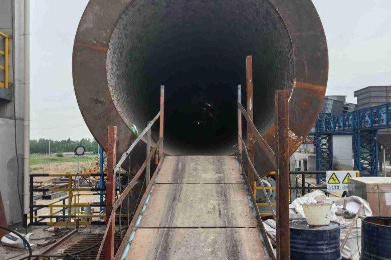
Calcium carbide furnace is the main equipment for producing calcium carbide. Calcium carbide furnace is a mineral heat furnace, the main raw material coke and limestone according to a certain ratio of requirements after mixing by electrode arc smelting reaction to produce calcium carbide (calcium carbide). Calcium carbide is produced in a calcium carbide furnace by melting the charge due to the high temperature emitted by the electric arc. Due to the reaction temperature of up to 2000℃ or more, such a high temperature, the general refractory is difficult to withstand. Therefore, the volume of the furnace body must be greater than the reaction space, that is, a layer of charge should be retained between the reaction zone and the lining to protect the lining.
There are many shapes of the furnace body, including round, oval, square and rectangular. From the thermodynamic point of view, circular furnace is more advantageous. In fact, the choice of furnace shape is mainly determined by the arrangement of electrode positions and the installation position of carbon monoxide extraction equipment. It can be said that most of today's calcium carbide furnaces are circular furnaces, and very few use other shapes.
The size of the reaction space in the furnace is determined by the size of the electrode, the distance and the arc range. The distance of the circular electrode is directly proportional to its diameter. The diameter of the electrode varies with the capacity of the furnace. The electrode diameter is determined by the current density it allows. The current of the electrode is determined by the transformer capacity. The final conclusion is that the size of the furnace body depends on the capacity of its transformer.
Calcium carbide is produced in the furnace due to the melting reaction of the charge due to the high temperature emitted by the electric arc. Due to the reaction temperature of up to 2000℃ or more, such a high temperature, the general refractory is difficult to withstand. So the volume of the furnace must be greater than the reaction space. That is to say, a layer of charge should be retained between the reaction zone and the lining to protect the lining.
The size of the reaction space in the furnace is determined by the size of the electrode, the distance and the arc range. The distance of the circular electrode is directly proportional to its diameter. The diameter of the electrode varies with the capacity of the furnace. The electrode diameter is determined by the current density it allows. The current of the electrode is determined by the transformer capacity. The final conclusion is that the size of the furnace body depends on the capacity of its transformer.
The size of the furnace and the distance between the electrodes are very important. When the size is selected appropriately, the current flows mostly from the electrode end through the reaction and melting layer to the bottom of the furnace. At this time, the operation of the calcium carbide furnace is very smooth. Otherwise, a large amount of current flows from one electrode through the charge interdiffusion layer and the preheating layer to the other electrode. In this way, the electrode can not go deep into the furnace, the furnace bottom temperature is reduced, the three phases in the furnace are not easy to smooth, the calcium carbide flow is difficult, and the operation of the calcium carbide furnace is deteriorated, which is very unfavorable to production.
The following is a brief introduction to the structure of the furnace body and the furnace door
(1) The requirements of the furnace shell for the furnace shell :① the strength of the furnace body should be able to meet the severe expansion of the furnace lining caused by heating, and adapt to the requirements of the furnace lining expansion and contraction; ② In the case of meeting the strength requirements, we should strive to save materials and reduce weight; (3) Convenient manufacturing, if necessary, the possibility of packaging and transportation should be considered.
(2) Filling layer: Usually the furnace wall brick lining is mostly wet masonry, and it expands when heated, so a layer of asbestos plate (or slag wool or dry sand) should be filled between the refractory brick and the iron shell. This layer is called the filling layer, also known as the buffer layer. The thickness of this layer depends on the size of the furnace, the masonry method and the nature of the refractory, which is generally 50 to 100 mm.
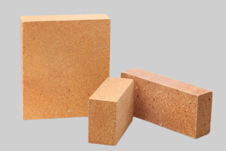
(3) Firebrick lining: six layers of firebrick are laid above the filling layer, and the thickness is about 450~500 mm. The wall of the furnace is laid with two layers of refractory bricks to the top of the furnace. Generally, clay refractory bricks are used, and there are two methods of building refractory bricks: dry building and wet building. The wet laying method adopts 70% refractory clinker powder, 30% refractory raw material powder, and water mixing masonry. The brick seam should not be greater than 3 mm. Dry laying method has higher technical requirements, so the dry laying method is mostly used on the large capacity calcium carbide furnace, and the furnace wall is wet laying method.
(4) Carbon brick lining: above the refractory brick layer, the thickness of the carbon brick layer varies according to the capacity of the calcium carbide furnace, the small capacity is 400~800 mm, the medium capacity is 800~1200 mm, and the large capacity is 1200~1500 mm. The masonry methods of carbon brick layer are divided into two kinds: coarse seam method and fine seam method. The rough seam method is to leave 30~50 mm brick cracks between bricks and bricks. The thick seam paste is heated into a paste, filled between the brick cracks, and then heated and tamped with a special tool and a pneumatic tool with a wind pressure of 3 to 7 kg /2 cm. The upper and lower brick seams should be staggered. Between the carbon brick and the fire brick, between the carbon brick and the top surface of the carbon brick layer should also be filled with a thick 50~100 mm thick seam paste. The fine seam method is to process carbon bricks into a plane with relatively high precision on the planer in advance. And pre-assembled in the processing plant, the tolerance size of each carbon brick is required to be ±1 mm. When laying on the calcium carbide furnace, the bricks and bricks are filled with melted fine seam paste, requiring that the brick seam is not greater than 2 mm. The fine seam method is the better of these two methods. However, the processing amount is large, so this method is generally only used on large capacity calcium carbide furnaces. It is easy to make coarse seam paste, but because of the volatiles volatilization during production, the holes between the brick cracks are easy to appear, and the permeability to prevent ferrosilicon is poor. In the large-capacity calcium carbide furnace, the brick lining at the lower end of the furnace wall is also made of carbon bricks, and the carbon brick between this layer and the carbon brick at the bottom of the furnace is also filled with a thin seam paste, the carbon brick is about 900 mm high and 400 mm thick. Corundum bricks are used near the furnace door to prevent oxidation of carbon bricks.
Leave a Message
Contact Us
Email: [email protected]
TEL: +86 13721425142

Clay brick is made by clay clinker and soft clay as a bond aluminum content of 30-48% stereotyped refractory. The particle composition of clay brick…

Under normal circumstances, the calcination belt uses bricks with a body density of more than 2.9, the transition belt uses 2.6 body density of ordinary…
Submit Request
PDF Request